The first major challenge encounter in trying to implement the video conferencing system was Microsoft Windows. Attempts to use a C-based program to directly access the QuickCam through the parallel port continually caused General Protection Faults and Fatal Exception errors for attempting to access hardware without going through the safeguards built into the operating system. Because the only solution to the problem was to purchase and use the Windows developer's API, and that would require additional time be spent to learn a new system, the decision was made to sidestep the problem. Instead of developing the prototype system for Windows, the switch was made to the Linux operating system. While working with the same hardware, within this Unix environment, the only obstacle to access to the parallel port was the file permissions on the device, something that was within the control of the system's owner. By developing for this platform, the ability to show the prototype working with the same hardware was made possible while leaving the implementation specifics of the Windows code to a localization issue, just as a port to the Macintosh or another operating system would be.
Concern as to the slowness of the Java versus C or C++ code were seen to be unfounded, both through subsequent references and first-hand and third-party experimentation. While the startup of the Java-based program is markedly slower than non-Java, once that initial overhead processing is complete, there is no significant difference. Additionally, due to the complexity of the interprocess communication needed by having multiple applets running per machine (due to Java applet security restrictions regarding access to local and remote resources), the decision was made to use a Java application, which is not subject to the applet security restrictions, and to integrate the network subsystem with the main body of Java code instead of using a separate C-based program.
The third and most troubling obstacle, however, was the Java language itself. While the langauge is powerful and flexible, it is also going through growing pains. Few people know it well and time has not had the time to sort through the various books and websites on the language to bring the good ones to light. Additionally, those that are available are often more focused on the use of Java applets to bring multimedia effects to a webpage and do not contain material about the many other features offered in the language. Therefore, given a problem which could normally be solved in hours, it often took days to find a Java solution, and often the remedy to the problem was a workaround rather than an actual solution. For these reasons, the decision had to be made to sacrifice the implementation of the audio subsystem to concentrate on the video and networking. This component would be left out of the prototype but could be implemented in a later version of the design.
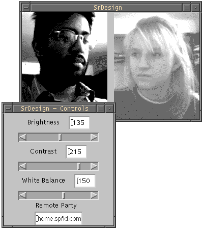
The implementation used includes custom written Java code to handle the user interface and networking. The interface consists of controls for the address of the remote host involved in the conference, as well as controls for the local brightness, contrast and white balance. This is implemented using a frame, which can be collapsed out of the way when not needed, containing text entry fields and scrollbars. Each of these controls modifies an Observable variable within the program. An Observable is a concept borrowed from SmallTalk to allow objects to express an "interest" in a variable allowing them to be notified upon any changes. This way, individual objects used within a program do not need to have knowledge about each other but can still safely share data without worrying about have garbage values caused by reading a variable while somebody else is writing to it.

The Java software also calls upon a custom written C-based shared library which integrates with the C-based "qcam" program written and published by Scott Laird and Jerry Kalkhof. This software is the defacto standard for controlling the QuickCam from a Linux system. A command string is constructed within the Java software, containing the current brightness, contrast and white balance levels selected by the user, and passed in a variable to the C function. The C function in turns uses this string to run the specified command, causing the qcam software to output a PPM format file and converting it into a GIF format image. This image is piped back into the C function where it is saved as a character array, which equates to a Java byte array and is made available to the main Java application.
Within the Java application, the byte array is converted into an image using the MemoryImageSource class which is part of the base Java language and drawn to the screen. The byte array is also converted into a User Datagram Protocol packet for transmission across the network. UDP was chosen due to the low overhead involved and the design criteria which state that it is more desirable to loose a packet every once in a while and see the most recently available image than it is to attempt to do error-correction and retransmission to ensure that every packet is sent and received. On the receiving side, the incoming UDP packet is saved into a second byte array and then, like the first array, undergoes the conversion to an image and is displayed.
The acoustical tracking system has essentially undergone a complete redesign. This is mainly due to the performance of the transducers. As described above, the transducers were to be placed a fixed distance apart so as to correlate the time difference of arrival for the two, with the angle of the transmitter. This method would have worked had the transducers been able to detect the time differences effectively. However, after repeated tests it was found that the transducers could only detect which side the transmitter was transmitting from (that is, which transducer triggered first), not the degree to which it was angled. That is to say, the transducers would give a constant value for the time difference. This meant that the only piece of information that could be gotten from the transducers was which side the transmission was from. As can be seen by the diagram below, there are three regions of interest when operating in this mode. One is the left side, the other is the right side, and the third is the so called "gray" area where values would fluctuate.
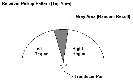
The redesign had to use this property (while trying to minimize the gray area). The first consideration was to minimize the gray area of uncertain values. Through experimentation an optimum mechanical mounting was achieved whereby the transducers were angled slightly away from each other. The amount of angling involved the tradeoff of having a small gray area while at the same time having good off-axis response. That is to say, it was desired to have the biggest range of operation for the user (both in terms of distance from the receiver and angle from the normal to the receiver).
Upon creating the proper mounting of the transducers, it was necessary to create a new algorithm to track the user. The original intent was to have the user press and release a button on the transmitter to cause the camera to track. The pressing of the button would send a pulse of sound out which would then arrive at the transducers at slightly different times. As mentioned previously, these time differences would then be used to determine the position of the user based on the arc-cosine relation. Due to the problem with the transducers, this method could no longer be used. Instead, the user would press and hold the button on the transmitter until tracking was complete. The receiver would check which transducer triggered first and then move the camera a fixed amount in that direction. Upon moving, the receiver would check again and continue the process until the opposite transducer triggered. The cycle would then be repeated for the vertical pair of transducers. Thus, the algorithm essentially makes the camera move until the transmitter crosses over the gray area into the opposite region, by using a simple feedback control algorithm. The reason that the user is required to continually press the button until tracking is complete, is that the software continually checks the triggering of the transducers after each move. The details of each subsystem are discussed in the following sections.
The transmitter circuit diagram can be found in the appendix. As can be seen it is a bit more complicated than originally expected due to the new algorithm for tracking. The overall block diagram is shown below.

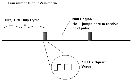
The transmitter's task is to essentially create a 40KHz square wave to drive the transducer. However, this 40KHz square wave is modulated by a 4Hz square wave to create four pulses per second of the 40KHz sound. The reason for this is that the microcontroller continually checks which transducer is triggering first, after it moves the camera. Thus a periodic beeping is needed to create valid triggering of the receiving transducers.
Both the 40KHz and 4Hz square waves are created by the 555 timer (a 556 chip was used, which contains two 555 timers). The outputs of these timers are fed into a series of NAND gates which create the modulated 40KHz signal. This modulated signal then enters a comparator which shifts the levels to +Vsat and -Vsat. This bipolar signal is then fed into a pair of BJTs in the Class B power amplifier configuration (with the load being the transducer). The output stage provides the necessary current gain to drive the transducer. Thus, when the user presses the button (which closes an opened ground connection), the transmitter "beeps" at 40KHz, four times a second. The timers were designed to create a wave of 250ms period (4Hz) with 25 ms of 40KHz transmission. Thus the duty cycle of the modulated wave is 10%. The diagram below shows the wave form.
The transmitter was soldered and packaged into a black box with a red button. This box can be placed in the user's pocket, and the transducer (which is connected to the box by means of 3 feet of stranded wire) can be clipped on to the user's clothing, around the torso area. The bulkiness of the box is due to the fact that there are four 9V batteries packaged into it. This high voltage is a requirement of the transducers.
The receiver circuit was also redesigned due to the unreliable operation of the previous design. The circuit diagram can be found in the appendix of this report. The overall block diagram is shown below.
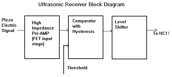
The first stage of the receiver is a non-inverting amplifier which serves as the pre-amp for the weak transducer signal (a 40KHz sinusoid). The original design used the LM324 general purpose op-amp for this stage. The LM324 was found to have an inadequate input impedance. This caused the signal to be loaded down significantly thereby causing the rest of the circuit to operate unreliably. Thus, the LF411 was chosen for the front end of the receiver due its very high input impedance (because of the FETs on the input side of the op-amp). The choice of the LF411 solved the problem completely.
The second stage of the op-amp is a Schmitt trigger. The Schmitt trigger replaced the simple comparator of the first design to filter out high frequency noise on the signal which would cause premature triggering. The threshold of the Schmitt trigger is set by a potentiometer feeding into an LM741 acting as a buffer. This potentiometer sets the overall sensitivity of the circuit. The optimum setting, balancing the tradeoff between range and accuracy proved to be at a setting of about 1V for the threshold. Once again the LM324 was used originally as the op-amp for this stage. However, it was seen on the oscilloscope that the output wave form was not a square wave as expected but more like a triangular wave. Upon concluding that the problem was with the fact that the op-amp did not have a high enough slew-rate, the LM324 was replaced with the NE531 by Signetics, which is a high slew rate op-amp. This proved to correct the problem and restored the expected square wave.
The final stage of the receiver performs level shifting by means of a reverse biased diode and a digital buffer. The reverse biased diode prevents the voltage from going negative by more than about seven tenths of a volt, while at the same time causing the positive voltage to be about 5 volts. The digital buffer creates a clean, isolated signal which is then fed in to the input capture pins of the HC11.
The receiver circuit needed significant design changes which included careful component selection and Schmitt triggering to perform reliably. These changes, however, have created a remarkable difference in performance in the circuit. It now consistently performs as expected.
The HC11 software (now rewritten to implement the new algorithm), is interrupt driven for increased reliability. It can be found in its entirety in the appendix.
The first part of the program initializes the interrupt driven operation based on the falling edges of the input capture pins. The program then enters a "wait for interrupt" stage. The two possibilities for interrupts at first are input capture 1 and input capture 2 ( which are connected to the horizontally aligned transducers on the camera). Thus the program will first align itself horizontally.
Both of these interrupt routines immediately wait for approximately 50ms, and then poll the input capture flags to see which one triggers first. The reason for this is that the transmitter is "beeping" four times a second. There is no reference as to where in the beep cycle the transmitter is when the software enters the interrupt. The triggering of the interrupt may have been done in the middle of a beep which could cause the opposite input capture pin to trigger. To insure that this does not happen the program waits 50ms to "jump over" the 25ms transmission time which triggered the interrupt and then waits for the next beep to come in. In this way, the beginning of the beep is what is used to determine which pin triggered first.
After polling, the program then stores a `1' or a `2' into accumulator A depending on which input capture triggered first after the 50ms delay. It then compares the current contents of accumulator A with a variable called "prev" which has the value of A from the previous call of the interrupt. If accumulator A and "prev" are the same the program moves the camera the fixed amount in the direction of the pin that triggered first and reenters the wait stage. If accumulator A is different than the value of "prev," this means that the camera has crossed the threshold and is now locked in place horizontally (horizontal motion is stopped). The process then repeats for the vertical motion. Upon completing both the horizontal and vertical tracking, the program waits until it senses that the transmitter is off. This means that the user has finally released the button. At this point the program initializes all variables, enters the "wait for interrupt" stage, and repeats the process indefinitely.
The motors obtained are 12V, 3.6 degrees per step, four phase, unipolar stepping motors. Originally, the system was designed for a resolution of two degrees or less, which would require half-stepping the motors. However, during tests, it was found that full stepping was more than sufficient to center the user and in turn executed the tracking faster. Each winding in the motor requires 150mA for proper stepping and the manufacturer included a driver schematic with suggested component values which was expanded upon to ensure proper usage of the motor while still meeting the system's needs.
The motors are controlled by the Motorola HC11 microprocessor through its
parallel ports. One motor uses the four least significant bits of Port C while
the other motor will occupy the least significant bits of Port B. Using a
convention of a and a' being the two ends of one winding and b and b' to be the
two ends of the other winding, the sequence for full stepping is:
a	1001	or	1000
b	1100	or	0100
a'	0110	or	0010
b'	0011	or	0001
where the first sequence requires more power, but the second sequence generates less holding torque since only one winding is energized at a time. In order to turn the motor in the other direction, the sequence is simply reversed.
Care must be taken in how fast the bits are sent to the motor and also how well we regulate the current to the windings. The main restriction for speed is the limit at which the camera can rotate without sacrificing the visual quality of the picture. This was determined by rotating the camera at different speeds and adjusting the speed according to visual preference. The output bit of the microprocessor acts as an enable which allows a regulated voltage through a resistor causing the draw of a small current, on the order of 1mA. This current is then amplified to a desired level for the winding by use of a current amplifying transistor.
The motor driving program first assigns symbol names to the proper address values of the output ports so that they can be easily recalled throughout the program and then calls initializing procedures to ensure that the motors' starting positions are known. Next, the direction of rotation necessary to center the user is read (having been calculated by the tracking device and another assembly program) and the status of the motion and step sequence is saved so that it is known for the next iteration.
Since the bulk of the motion done by the user will be lateral as opposed to vertical, horizontal sweeping is implemented prior to vertical sweeping. Once the motor begins to step in one direction, the routine will continue to be called until the user is centered. The directional information is stored by one bit. By reading this bit, the program can jump to either the forward rotation loop or the reverse rotation loop. After rotation is complete, the program saves the status of the horizontal position by storing two pieces of information: the pointer of the step sequence and the number of the step sequence. The pointer is used to ensure that the next step in the sequence is used next and the sequence number is used to keep track of when the cycle starts over. The stored value of the pointer is that of the step on hold, then the pointer is increased or decreased just before the next step is taken. The vertical movement follows the same principles.
The motor program is setup as four separate subroutines which can be called by a main program. The main program is the tracking program. which contains delay instructions between the steps, used because the motor cannot step as fast as the microprocessor carries out instructions. The amount of delay time was determined by how fast it was desired that the motors rotate. The delay time turned out to be .05 seconds between steps, by experimentation. This actually makes it so that an observer cannot distinguish between the two steps that are taken at a time before the polling is done to determine if we have successfully tracked the user.
Another feature is the use of a software stop of rotation. This means that the program keeps track of the number of steps it has taken in each direction and makes sure that it does not exceed a defined limit. The limit for horizontal rotation is 86 degrees left or right and the limit for vertical rotation is 42 degrees up and down. This limit is designed to ensure that the camera does not spin completely around and get wrapped up in the wires.
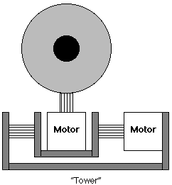
The mechanical aspects of mounting the camera were greatly simplified when it was learned that the QuickCam is capable of being mounted to a standard tripod through a threaded screw harness. This made fastening the camera to the rotating body easy and also allowed for a simplified mechanical design. The actual assembly of the system uses plexi-glass which is a very lightweight, low cost material. The plexi-glass is fastened via epoxy and the motors are mounted directly to the glass. Each motor has a hollow rod with a set screw connected to its rotor and this rotor is attached to the rotating body. For one motor, the rotating body is simply the QuickCam; the rod was threaded with 1/4" 20 tread and screwed into the standard tripod mount hole on the camera. The second rod is fastened to a cradle which houses the other motor. When this cradle rotates, it moves both the motor and the camera. The receivers are attached to the rod which screws into the camera so they rotate with the camera. This is done so that the receiver matrix is always aligned with the camera's perspective to ensure proper tracking.
